How to drive a 7 segment display directly on Raspberry Pi in Python

 Last week I bought some 4-digit, 7-segment displays to experiment with. Strangely enough it was something I’d never tried before, so I was interested to see how they work. I googled around looking to see if someone else had done this before. It seems there are several different sorts of 7-segment displays, so you have to find a good match for the one you’ve bought.
You can get them in various guises including: i2c backpack; 12 pins; 16 pins; resistors built-in; common anode; common cathode etc.
The ones I bought are 12 pin, bare, no backpack, no PCB, no resistors, common cathode. Here’s what they look like…

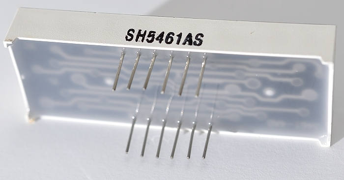
7-segment display – rear
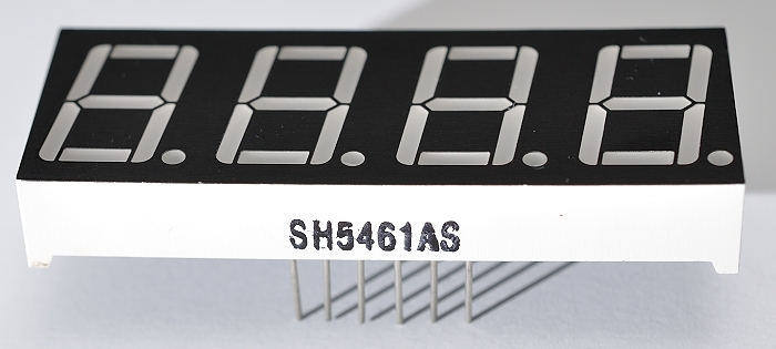
7-segment display
No Datasheet? Google Is Your Friend.
There was no datasheet, so I had to dig around for information. I found two really useful pages which gave me all I needed to know. One was on the Parallax website, which gave me the pinouts, from which I’ve made my own pinout diagram showing the pin numbers and what they do…

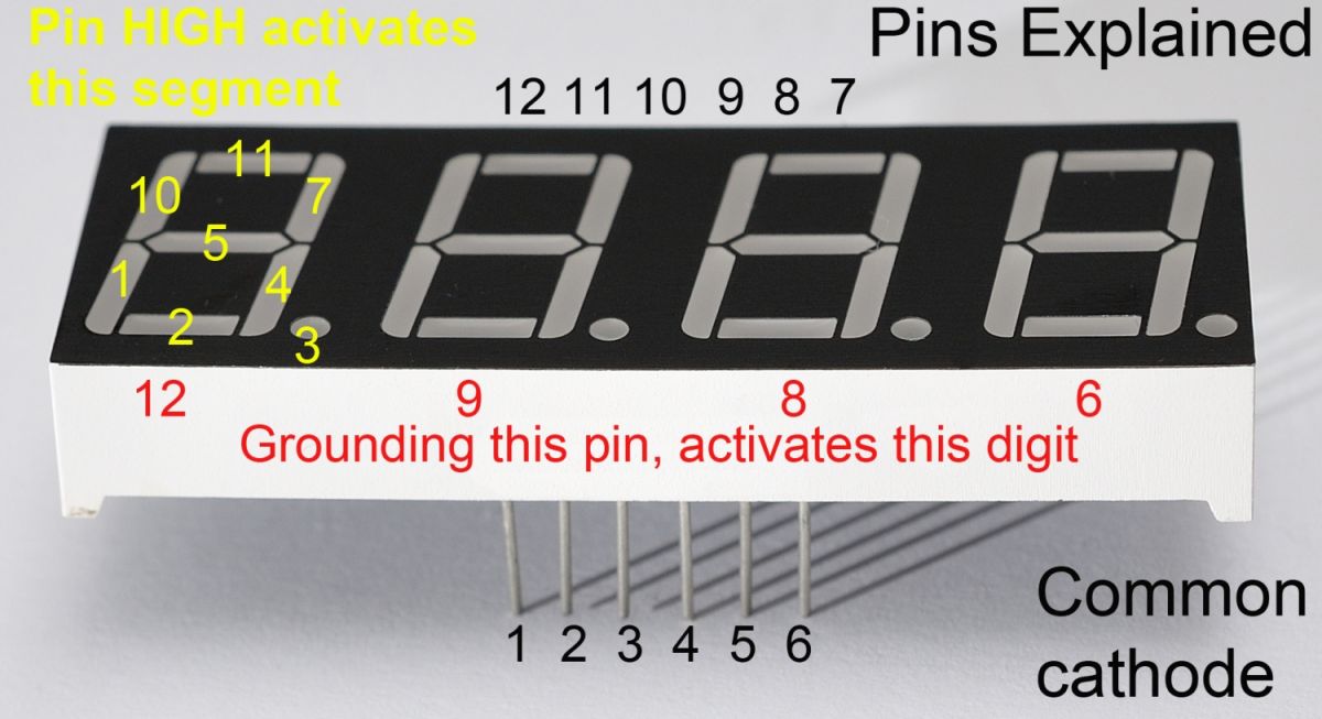
Common cathode 4-digit 7-seg pinouts
How Does It Work?
If you connect pin 12 to GND, the first digit will activate (9 = second, 8 = third, 6 = fourth).
Bringing each of the other 8 pins HIGH activates a specific segment on all currently active digits.
So if we had 12, 9, 8 & 6 all connected to GND, and 7 & 4 HIGH, all four digits would display the number 1.
But How Can We Use That? It’s Impossible?
The way that you get each digit displaying something different is to switch them on and off again, in turn, faster than the eye can observe. Using the same circuitry to control more than one ‘thing’ is called multiplexing. We need some Python code to handle this for us, and we’ll do it using 12 of the Pi’s GPIO pins (4 to switch the digits and 8 to switch the segments).
We also need some current-limiting resistors. 330 Ohm works, but is a bit dim. I’ve opted for 100 Ohm, which gives the LEDs a little protection. In reality, we’re switching fast, so each segment should only be ON for a short time. But if you connect these segments directly to a 3V3 source off-Pi without current-limiting resistors, you will damage or kill the leds in the segments (yes of course I tried it).
OK Let’s Wire It Up!
Here are the connections you need to make…
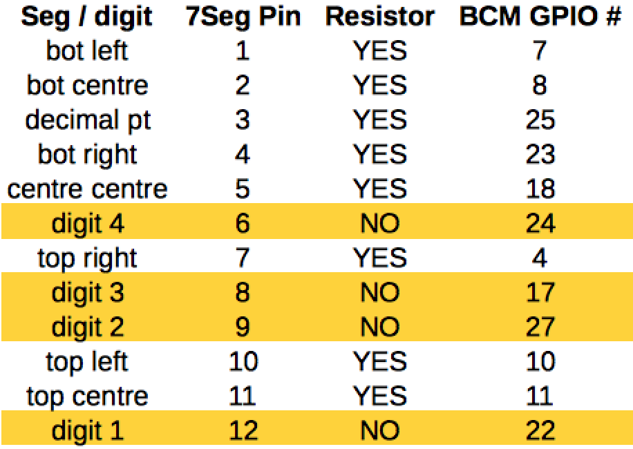
Wiring connections for common cathode 7-segment display
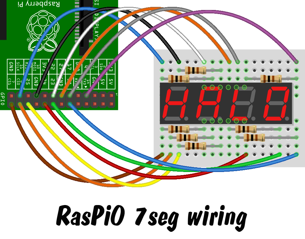
Wiring Diagram for 7-segment display
This is what my finished setup looks like (not quite as pretty as the diagram)…
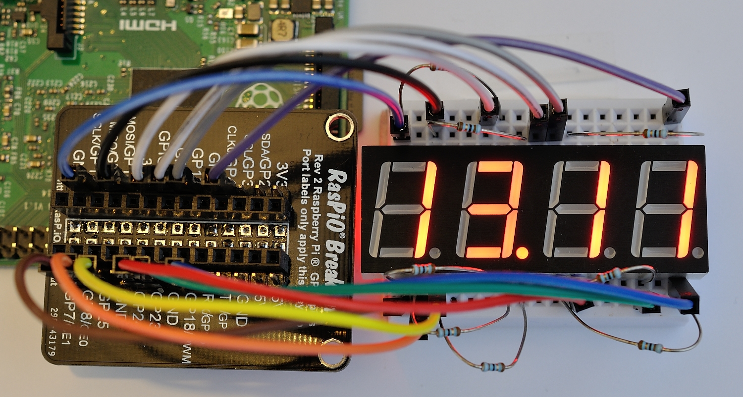
RasPiO 7-segments display clock
I used one of my RasPiO® Breakout boards and a 170 point mini-breadboard to wire up the 7-segment display. This means you can do all the wiring “off-Pi” and then attach the project all at once. For a 12-wire project, this is extremely useful. I wired it directly to the Pi the first time, but when I wanted to re-order the wiring, I found it much easier to use the RasPiO® Breakout. It’s also easy to detach from the Pi without undoing and messing up all the wiring.
What About The Code?
The other useful web page I found was a post in the Raspberry Pi Forums, where Bertwert had published a Python script to turn one of these displays into a clock. That looked like a fun way to test out the new toys, so I gave it a try. I very carefully wired everything up exactly according to the instructions, but only one digit was lit. I checked my wiring. It looked sound. I had another look and eventually realised that the code posted in the forum had messed up indents.
This is one of the hazards of cutting and pasting code, and particularly Python. What it meant was that only one digit was being processed, the others were being passed over. Adding a few well-placed indents helped this to work correctly. There was also a missing colon in the code that caused it to throw an error. As you do, I posted back my amended code for future followers of that thread.
I also tweaked it to eliminate a redundant line, converted it to use BCM GPIO numbers and changed the wiring to make it logical for my chosen layout. The code is posted below…
# code modified, tweaked and tailored from code by bertwert
 # on RPi forum thread topic 91796
 import RPi.GPIO as GPIO
 import time
 GPIO.setmode(GPIO.BCM)

# GPIO ports for the 7seg pins
 segments = (11,4,23,8,7,10,18,25)
 # 7seg_segment_pins (11,7,4,2,1,10,5,3)   100R inline

for segment in segments:
 GPIO.setup(segment, GPIO.OUT)
 GPIO.output(segment, 0)

# GPIO ports for the digit 0-3 pins
 digits = (22,27,17,24)
 # 7seg_digit_pins (12,9,8,6) digits 0-3 respectively

for digit in digits:
 GPIO.setup(digit, GPIO.OUT)
 GPIO.output(digit, 1)

num = {' ':(0,0,0,0,0,0,0),
 '0':(1,1,1,1,1,1,0),
 '1':(0,1,1,0,0,0,0),
 '2':(1,1,0,1,1,0,1),
 '3':(1,1,1,1,0,0,1),
 '4':(0,1,1,0,0,1,1),
 '5':(1,0,1,1,0,1,1),
 '6':(1,0,1,1,1,1,1),
 '7':(1,1,1,0,0,0,0),
 '8':(1,1,1,1,1,1,1),
 '9':(1,1,1,1,0,1,1)}

try:
 while True:
 n = time.ctime()[11:13] time.ctime()[14:16]
 s = str(n).rjust(4)
 for digit in range(4):
 for loop in range(0,7):
 GPIO.output(segments[loop], num[s[digit]][loop])
 if (int(time.ctime()[18:19])%2 == 0) and (digit == 1):
 GPIO.output(25, 1)
 else:
 GPIO.output(25, 0)
 GPIO.output(digits[digit], 0)
 time.sleep(0.001)
 GPIO.output(digits[digit], 1)
 finally:
 GPIO.cleanup()
There’s a full code walk-through in the comments below.
Want To Have A Go?
If you’d like to have a go at this project, I have a limited number of kits available for £12 including global shipping. Here’s what’s in the kit. Pick yours up today and start playing with 7-segment displays on your Pi…

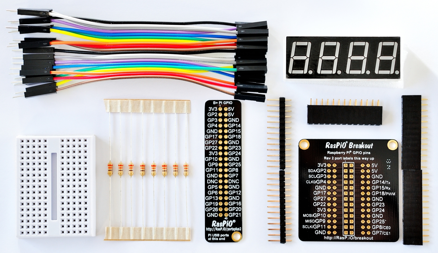
RasPiO 7-segments display tinkering kit
Source: RasPI.tv