People or Object counter Circuit diagram using IC 555 and IC 4026

People / Object counter circuit have a wide variety of applications in Banks, Hospitals, factories etc. This project focuses on building an effective counter using IR as a sensing element and capable of counting from 0 to 999. This project uses Two simple IC’s ( IC 555 & IC 4026 ) with IR transmitter and Receiver to detect the incoming people/object.
This Project comprises of Three parts
IR TRANSMITTER:

Freq = 1.45 / ( R3 + 2R1 ) C2IR transmitter was wired around Astable multivibrator using IC 555. As we all know that multivibrator produce square wave pulses and we gotta fix the frequency of the output signal as 38 Khz since we are about to use TSOP 1738 an Infra red sensor which is capable of detecting signals of 38 Khz. The frequency of the astable depends on R1,R3 and C2. So lets do some math
= 1.45 / (470 + 2 * 1690 ) * 100 * 10
= 37.6 Khz
So we have fixed the IR frequency of 38 Khz and now Transmitter part is done.
Please note that i have used a simple IR transceiver module (brown board – right top) for this project to make things simple. You can use use IR module like i did if you have any. If not build the IR transmitter using IC 555 as shown in above circuit. The receiver part was given in the below circuit diagram.
IR RECEIVER AND 7 SEGMENT DRIVER: 

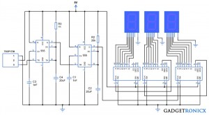
The sensed output was fed into trigger input of the monostable multivibrator using IC 555. As we all know that Multivibrators gives high output when low signal as fed into its trigger and low output when high signal is fed. Two multivibrators was cascaded to prevent multiple increments in the counter since using a single multivibrator changes the output with every low to high or high to low transition in trigger pin.The above circuit diagram comprises of both Infra Red Receiver as well as 7 segment driver. The IR signal is sensed by TSOP 1738 which is capable of sensing the IR signals of 38 Khz frequency. This TSOP will give high signal as output when IR signal is sensed and low signal when IR falls on it. The third pin of the TSOP gives the output and its fed into next stage of the circuit.
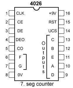 |
| IC 4026 |
Next stage of the circuit is 7 segment drivers which is done by three IC 4026 which is a 7 segment display decade counter. This IC is capable of incrementing the digits in 7 segment with clock input in the CLK pin. The output from the monostable multivibrator forms the clock source for this IC 4026. Read more about 7 Segment interface with IC 4026.
WORKING:
The transmitter and Receiver was initially aligned and this makes the TSOP 1738 to give low signal to the multivibrator which in turn gives high at the output and this forces the 2nd Multivibrator to give low signal to the CLK pin of the right most IC 4026. When the IR beam in interrupted the TSOP gives high output which in turn makes the Multivibrator 1 to give low signal trigger to the 2nd multivibrator.
The low signal input pushes the output of Multivibrator 2 to high state thereby a successful transition occurs and this forms a single clock pulse input to the IC 4026. Thus this makes the IC to increment a single value in the 7 segment. Now cascading three segments will enable us to display count up to 999 which was done by connecting the CO (Clock Out) pin of the IC 4026 to the input clock pin of the preceding IC 4026.
Whenever IC 4026 finishes counting from 0 to 10 it gives out a logic transition in its CO pin which sources the clock for preceding IC at CLK pin which in turn increments the value by 1. By this way three IC’s work together to display digits from 000 to 999.
NOTE:
- You can increase the count value by adding 7 segments along with IC 4026 by connecting the CO pin output of the Preceding IC to its CLK pin.
- You must use two multivibrator or else you will obtain two increments for a single incoming person/object.