Archive

Archives pour la catégorie ‘Matériel’

Disjoncteur

20/08/2022 Comments off

Un disjoncteur est un dispositif électromécanique, voire électronique, de protection dont la fonction est d’interrompre le courant électrique en cas d’incident sur un circuit électrique. Il est capable d’interrompre un courant de surcharge ou un courant de court-circuit dans une installation. Suivant sa conception, il peut surveiller un ou plusieurs paramètres d’une ligne électrique. Sa principale caractéristique par rapport au fusible est qu’il est réarmable (il est prévu pour ne subir aucune avarie lors de son fonctionnement).

Différentes techniques utilisées par les disjoncteurs

Thermique

Ce type de disjoncteur se déclenche quand un courant excessif traverse un bilame, créant un échauffement par effet Joule et provoquant sa déformation. Ce bilame déclenche mécaniquement un contact, qui ouvre le circuit électrique protégé. Ce système électromécanique est assez simple et robuste mais n’est pas très précis et son temps de réaction est relativement lent. Il permet donc d’éviter de mettre le circuit en surintensité prolongée. La protection thermique a pour principale fonction la protection des conducteurs contre les échauffements excessifs pouvant générer des risques d’incendies, dus aux surcharges prolongées de l’installation électrique.

Il remplit la même fonction qu’un fusible, lequel doit être remplacé après avoir coupé le courant.

Magnétique

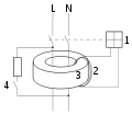
La forte variation d’intensité passe au travers des spires d’une bobine (repère 7 sur la photographie « Éclaté d’un disjoncteur »). Elle produit, selon les règles de l’électromagnétisme, une forte variation du champ magnétique. Le champ ainsi créé déclenche le déplacement d’un noyau de fer doux qui va mécaniquement ouvrir le circuit et ainsi protéger la source et une partie de l’installation électrique, notamment les conducteurs électriques entre la source et le court-circuit.

L’interruption est « instantanée » dans le cas d’une bobine rapide ou « contrôlée » par un fluide dans la bobine qui permet des déclenchements retardés. Il est généralement associé à un interrupteur de très haute qualité qui autorise des milliers de manœuvres.

  • Ce fonctionnement peut remplacer le fusible sur les courts-circuits.
  • Suivant le type de disjoncteur, la valeur d’intensité de consigne va de 3 à 15 fois l’intensité nominale (pour les modèles courants).
  • De nombreuses autres possibilités existent, déclenchement par bobine tension (consigne provenant de capteurs), interrupteur/disjoncteur pour montage face avant, compatible bitension 100/220 volts, bobine sous voltage (disjoncteur maintenu à partir d’une consigne tension), déclenchement à distance, réarmement à distance.
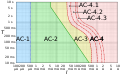
  • Nombreuses courbes de déclenchement pour CC, CA 50/60 Hz et 400 Hz.
  • Une option étanche est généralement disponible, soit version face avant étanche, soit entièrement (IP67).

C’est la fonction remplie par un fusible aM (accompagnement moteurs). Pour démarrer, un moteur demande, pendant quelques instants, une brève surintensité pouvant aller jusqu’à dix fois son intensité normale de fonctionnement. Cette surintensité, normale, ne doit toutefois pas déclencher le dispositif de protection. Ainsi, les fusibles de type aM sont conçus pour pouvoir absorber pendant un court instant un pic d’intensité supérieur à la valeur de protection. En revanche, en cas de surintensité (d’une valeur inférieure mais plus longue) : le dispositif coupera logiquement l’alimentation électrique.

La protection magnétique a pour principale fonction la protection des équipements contre les défauts (surcharge de l’équipement, court-circuit, panne…). Il est choisi par l’ingénieur qui a le souci de protéger son équipement avec une très grande précision.

Lire la suite…

HP-41C/CV/CX

16/06/2022 Comments off

HP 41C front viewAround the time of the HP-67, an article in the Hewlett-Packard Journal, stated that electronic technology was no longer the only limitation of pocket calculator progress. The human interface was becoming an even greater barrier to adding more functionality. The HP-67 was an excellent example of the problem. It had three shift keys and most of its other keys had four functions. HP was running out of keyboard space for new functions, and many users found it difficult write and use numeric-only programs.

The HP-41C overcame these limitations by adding alphanumeric capabilities to both the display and keyboard. The keyboard had an “Alpha” key that toggled the keyboard between alpha and the normal calculator mode. (The alpha characters were printed on the slanted faces of the keys.) If the user needed a function not printed on a key, the name of the function could be typed in and executed. (About half of the HP-41Cs functions were preassigned to keys.)

Because typing out the name of a function could be cumbersome, the HP-41C added another toggle key called “user”. The user could assign any built-in function or user program to any key. Once the keyboard was placed in user mode, any assignments made by the user overrode the label on the key. (With the gold shift key, this allowed two user functions per key.) The user toggle state remained set even when the calculator was turned off allowing true keyboard customization.

To make it easy to remember keyboard assignments, HP provided keyboard overlays along with preprinted labels for all built-in functions and blank labels for user functions. In addition, whenever a key was held down, its function name was displayed. If it was the wrong key, the user could continue to hold it until the display showed “NULL” when meant the function was canceled.

Of course, HP didn’t just improve the human interface. The HP-41C had more memory (now non-volatile) than its predecessor, more functions, improved programming, and could be expanded with both RAM and ROM modules.

From The Introduction:

“The HP-41C represents a totally new concept in the design of Hewlett-Packard calculators. In fact, because of the advanced capabilities of the HP-41C, it can even be called a personal computing system. The HP-41C is the first Hewlett-Packard handheld calculator offering an exciting array of alphanumeric capabilities.With so many different kinds of calculator uses and applications in the world, we at Hewlett-Packard decided we could provide a significant contribution by designing and building you aquality calculator with expandable and flexible capability. The alphanumeric HP-41C is just the calculator.”

Alphanumeric Implementation

The HP-41C used a low power LCD display with 7 more segments than previous calculators. This allowed a full range of alphabetic characters. The characters were not as fully formed as a dot matrix display, but they had better contrast.

There was a special register on the HP-41C called the Alpha Register. It allowed up to 24 characters. This register was separate from the stack and the other storage registers. Alpha strings could be stored in normal registers or the stack but they were truncated to 6 characters when this was done. A function that shifted strings by 6 characters was included to make it easy to store long strings in multiple registers.

Expansibility

Cassette readerThe HP-41C came with 63 “registers” of memory. Memory could be dynamically reassigned between storage registers and program memory. (63 registers was equal to 200-400 fully merged lines of program memory.)

Four ports at the top end of the machine allowed the user to plug in 4 more RAM modules which would increase the maximum register space to 319 or allow 1000-2000 lines of program space. (Or any compromise between those.) Later, the entire register space could be provided via a single “Quad Memory” module and Extended Memory was added to allow even more space..

The Optional Card Reader/Writer (82104A)

Card reader, ROM module and faceplateBecause the HP-41C had continuous memory and because its application pacs came on ROM modules, a card reader was omitted. However, one could be plugged into the top end. (In less time then it takes to read this sentence.) The HP-41C was obviously not code compatible HP-67, however, a sophisticated translator was built into the card reader which translated programs to HP-41C code on the fly.

Lire la suite…

Categories: Matériel Tags:

If your iPhone, iPad, or iPod touch won‘t turn on or is frozen

30/10/2017 Comments off

If your device has a frozen screen or doesn’t respond when you touch it, or becomes stuck when you turn it on, learn what to do.

If your screen is black or frozen

If your screen is black or frozen, you might need to force restart your device. A force restart won’t erase the content on your device. You can force restart your device even if the screen is black or the buttons aren’t responding. Follow these steps:

  • On an iPhone 8 or iPhone 8 Plus: Press and quickly release the Volume Up button. Then press and quickly release the Volume Down button. Finally, press and hold the Side button until you see the Apple logo.
  • On an iPhone 7 or iPhone 7 Plus: Press and hold both the Side and Volume Down buttons for at least 10 seconds, until you see the Apple logo.
  • On an iPhone 6s and earlier, iPad, or iPod touch: Press and hold both the Home and the Top (or Side) buttons for at least 10 seconds, until you see the Apple logo.

If your device still won’t turn on or start up

Plug in your device and let it charge for up to one hour.

After a few minutes, you should see the charging screen. 


If you don’t see the charging screen within an hour, or you see the connect to power screen, check the jack, USB cable, and power adapter. Make sure that everything is plugged in firmly, free of debris, and not damaged. You might want to try a different USB cable or power adapter.

If your device still doesn’t turn on, see what to do next.

If your device turns on but gets stuck during start up

If you see the Apple logo or a red or blue screen during startup, try these steps:

  1. Connect your device to a computer and open iTunes. If you don’t have a computer, try to borrow one, or go to an Apple Store or Apple Authorized Service Provider for help. 
  2. While your device is connected, force it to restart. 
    • On an iPhone 8 or iPhone 8 Plus: Press and quickly release the Volume Up button. Then press and quickly release the Volume Down button. Finally, press and hold the Side button until you see the recovery-mode screen.
    • On an iPhone 7 or iPhone 7 Plus: Press and hold the Side and Volume Down buttons at the same time. Keep holding them until you see the recovery-mode screen.
    • On an iPhone 6s and earlier, iPad, or iPod touch: Press and hold both the Home and the Top (or Side) buttons at the same time. Keep holding them until you see the recovery-mode screen.
  3. Don’t release the buttons when you see the Apple logo. Keep holding until you see the recovery mode screen.


  1. When you get the option to restore or update, choose Update. iTunes will try to reinstall iOS without erasing your data.

iTunes will download the software for your device. If it takes more than 15 minutes, your device will exit recovery mode and you’ll need to repeat steps 2 and 3.

 
Categories: Constructeur, Matériel Tags: ,

People or Object counter Circuit diagram using IC 555 and IC 4026

26/06/2017 Comments off

People / Object counter circuit have a wide variety of applications in Banks, Hospitals, factories etc. This project focuses on building an effective counter using IR as a sensing element and capable of counting from 0 to 999. This project uses Two simple IC’s ( IC 555 & IC 4026 ) with IR transmitter and Receiver to detect the incoming people/object.

This Project comprises of Three parts

  1. IR Transmitter
  2. IR Receiver
  3. 7 Segment drivers

IR TRANSMITTER:

Freq = 1.45 / ( R3 + 2R1 ) C2IR transmitter was wired around Astable multivibrator using IC 555. As we all know that multivibrator produce square wave pulses and we gotta fix the frequency of the output signal as 38 Khz since we are about to use TSOP 1738 an Infra red sensor which is capable of detecting signals of 38 Khz. The frequency of the astable depends on R1,R3 and C2. So lets do some math

         = 1.45 / (470 + 2 * 1690 ) * 100 * 10

         = 37.6 Khz

So we have fixed the IR frequency of 38 Khz and now Transmitter part is done.

Please note that i have used a simple IR transceiver module (brown board  – right top) for this project to make things simple. You can use use IR module like i did if you have any. If not build the IR transmitter using IC 555 as shown in above circuit. The receiver part was given in the below circuit diagram.

Lire la suite…

Categories: Électronique, Matériel Tags:

Residual-current device

21/06/2017 Comments off
From Wikipedia, the free encyclopedia
 

An RCD does not provide protection against unexpected or dangerously high current (called spikes or surges) when current is flowing in the usual wires in the circuit, therefore it cannot replace a fuse or protect against overheating or fire risk due to overcurrent (overload) or short circuits if the fault does not lead to current leakage. Therefore, RCDs are often used or integrated as a single product along with some kind of circuit breaker, such as a fuse or miniature circuit breaker (MCB), which adds protection in the event of excessive current in the circuit (the resulting RCD with overcurrent protection called an RCBO). RCDs also cannot detect the situation where a human accidentally touches both conductors at the same time, since the flow of current through an expected device, an unexpected route, or a human, are indistinguishable if the current returns through the expected conductor.

RCDs are usually testable and resettable devices. Commonly they include a button that when pressed, safely creates a small leakage condition, and a switch that reconnects the conductors when a fault condition has been cleared. Depending upon their design, some RCDs disconnect both the energized and return conductors upon a fault, while others only disconnect the energized conductor and rely upon the return conductor being at ground (earth) potential. The former are commonly known as “double-pole” designs; the latter as “single-pole” designs. If the fault has left the return wire “floating” or not at its expected ground potential for any reason, then a single-pole RCD will leave this conductor still connected to the circuit when it detects the fault.

[one-third-first]A two-pole, or double-pole, residual-current device. The test button and connect/disconnect switch are colored blue. A fault will trigger the switch to its down (off) position, which in this device would disconnect both conductors.[/one-third-first]
[one-third]

  • Log-log graph of the effect of alternating current I of duration Tpassing from left hand to feet as defined in IEC publication 60479-1.[1]

[/one-third]
[one-third]

1: Electromagnet with help electronics
2: Current transformer secondary winding
3: Transformer core
4: Test push-button
L: Line conductor
N: Neutral conductor

[/one-third]

Lire la suite…